3.1 How a Circuit Represents 0 and 1
In the previous chapter, we looked at how a computer operates in the abstract. Now it’s time to see how those operations actually happen. At the heart of it is the chip. To look inside a chip, we first need to understand circuits — because, as you’ll come to see, a chip is ultimately a very small and very complex circuit. So let’s start with the circuit itself. Figure 3-1 shows the kind of electric circuit most of us first met in upper elementary or middle school. There’s a light bulb, a battery, and a switch. Most of us know that pressing the switch makes the bulb light up.
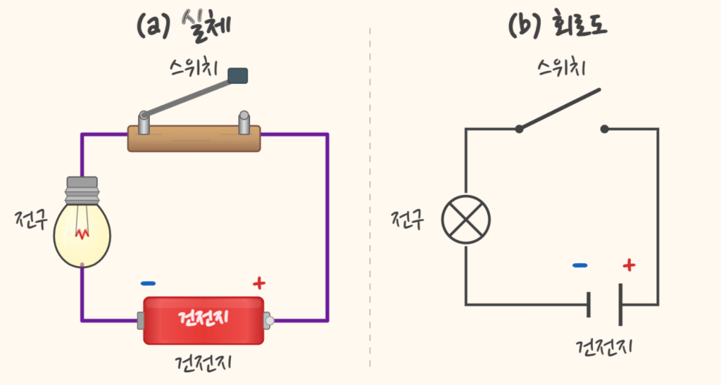
A circuit is a path connected so that electricity can flow. It’s easy to picture as a channel that water runs through. What flows along this channel is current — more precisely, a flow of electric charge. When current flows, each component connected to the circuit does its job: the bulb gives off light, the motor turns. The switch is a little different. It isn’t a component that does work with the current; it’s a component that connects or breaks the channel, deciding whether current flows at all.
Besides current, there’s one more thing worth noticing in a circuit. Look again at the battery in Figure 3-1. Even when the switch is open and no current flows, there is a voltage between the battery’s two terminals. Voltage can be likened to the “push” that makes current flow.
Voltage is similar to water pressure. In the channel analogy, the battery is a pump pushing the water, and the switch is the spot where the channel is connected or cut. Figure 3-2 redraws the circuit of Figure 3-1 with the wiring replaced by water channels. When the switch is closed, the water level at measuring point P rises; when it’s open, the level falls. What matters here is not whether the water is flowing, but how full point P is. In this figure, the height of the water level stands for the height of the voltage.
Now let’s set a threshold and agree to call it 1 when the voltage is above it and 0 when it’s below.
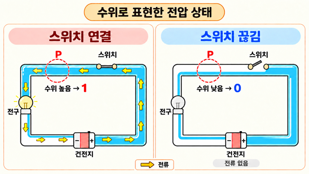
This agreement may seem trivial, but it matters because it turns the electrical state of a circuit into numbers people are familiar with. We can now look at any point in a circuit not in terms of high or low voltage, but as 0 or 1 — and, conversely, we can represent the numbers 0 and 1 with the voltages of a circuit. This is what it means to represent information with the state of a circuit.
For example, reading the voltages at the six points of the circuit in Figure 3-3 in order gives low, high, low, low, high, low. Translated according to our agreement, that’s 010010 — in other words, the circuit’s current state represents the information 010010.
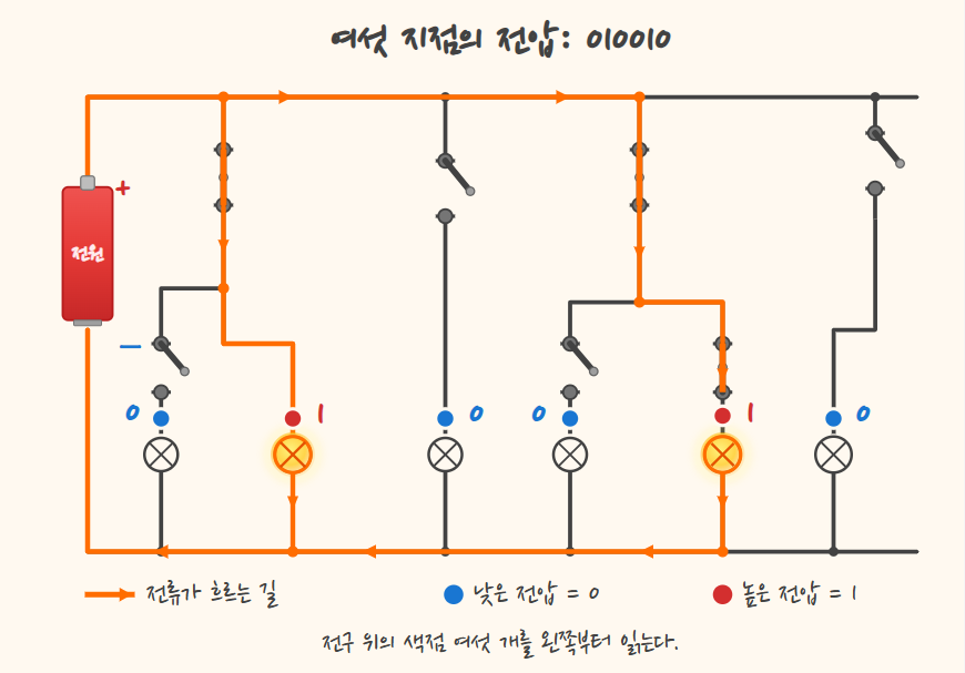
And so we can now represent 0 and 1 with a circuit’s voltages. From here on, whenever 0 and 1 appear in a circuit, be sure to remember that they are not numbers in themselves, but the circuit’s voltage states mapped onto the numbers 0 and 1.