3.5 Basic Logic Circuits Built from Transistors
In the previous section, we looked at a way of thinking that links the behavior of electronic circuits to our own calculations. Building on that perspective, let’s now see what kinds of circuits we get by connecting transistors. Even the complex circuits inside a chip are, in the end, made up of many small circuits like these.
First, let’s look at circuits that perform simple logical operations (logic circuits).
Boolean algebra, a branch of mathematics developed in the mid-19th century, deals with logical operations. The familiar addition operation takes 1 and 2 and answers 3; in a similar vein, a logical operation takes true or false values as input and answers true or false. There are several kinds of logical operations, such as AND, OR, and XOR. What we’ll look at now are electronic circuits that perform these operations.
As we saw in the previous section, an electronic circuit that performs an operation is nothing special: it is simply a circuit in which the operation’s inputs and outputs are mapped onto the circuit’s inputs and outputs, built so that the desired inputs produce the desired outputs.
Of the many logical operations, let’s look at an electronic circuit for the most representative one, AND. First, we need to understand the AND operation itself. AND takes two inputs and gives true (True) as its result only when inputs A and B are both true; in every other case, the result is false (False). For example, if input A is true and input B is false, the result of A AND B is false. Table 3-2 summarizes the inputs and results of the AND logical operation.
| A (input) | B (input) | Result |
|---|---|---|
| False | False | False |
| False | True | False |
| True | False | False |
| True | True | True |
A table like this, listing every possible combination of inputs together with the result, is called a truth table. Table 3-2 shows the inputs of the logical operation and the result for each. If there is an electronic circuit that corresponds to this operation — that is, one that produces the same results — then that circuit is an electronic circuit that performs the AND operation.
As we agreed in Section 3.1, an electronic circuit represents a voltage below the threshold as 0 and above it as 1. If we further map true (True) to 1 and false (False) to 0, we can relate true and false to the circuit as well, and start thinking about a circuit that produces the same results as the AND operation.
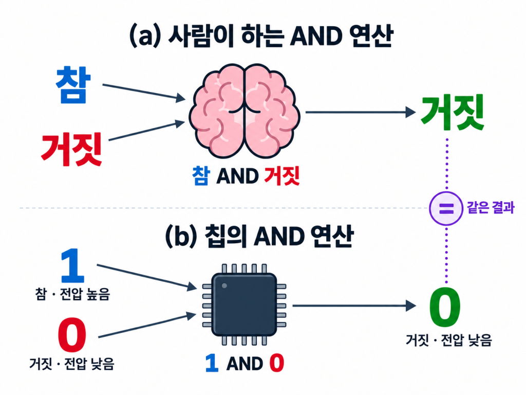
Imagine building a circuit with the inputs and outputs shown in Figure 3-9 by connecting transistors. Is that really possible?
In fact, without pointing it out at the time, we already met an electronic circuit that performs the AND operation back in Section 3.2. Look at the four cases in Table 3-1, which summarized the inputs and outputs of the circuit in Figure 3-5, and you’ll see that they produce exactly the same inputs and outputs as Table 3-2 above. This means that the circuit is capable of the AND logical operation. With the circuit in Figure 3-5, we can say that we built an AND logic circuit by connecting two transistors.
Now that we have a logic circuit that performs AND by suitably connecting two transistors, we can use it to get fast and accurate results for the AND operation. We no longer have to work out the result in our heads, and there’s no need to memorize the table. With the electronic circuit, we simply apply voltages to the inputs as we wish; the circuit sets the output voltage to the appropriate result, and by reading it, we immediately know the result of the AND operation. With this, an electronic circuit can take the place of human calculation.
In the same way, let’s look at a circuit that performs the OR logical operation. Unlike AND, OR gives true (True) as its result if even one of its inputs is true. As we did for the AND circuit, let’s summarize the inputs and results of OR in Table 3-3. Then think about how transistors could be connected to make an electronic circuit that performs OR.
| A (input) | B (input) | Result |
|---|---|---|
| False | False | False |
| False | True | True |
| True | False | True |
| True | True | True |
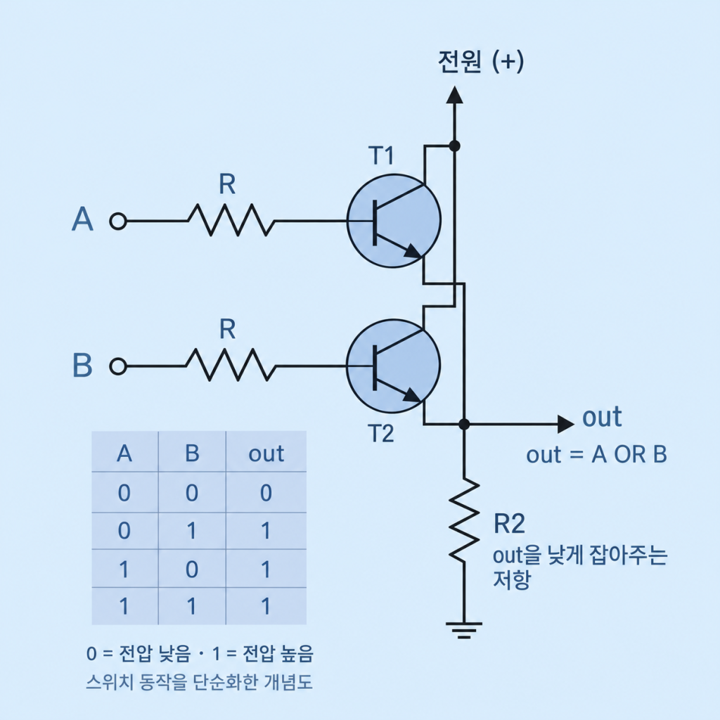
Trusting that you’ve taken some time to think it over, look at Figure 3-10: it is an OR logic circuit built by connecting two transistors.
In this circuit, C of both transistors T1 and T2 is connected to the power supply, so its voltage is high, and E of both transistors is connected together to out. When input A applies voltage to B of T1, T1 closes regardless of input B, out is connected to the power supply, and out’s voltage rises. Likewise, when input B applies voltage to B of T2, T2 closes regardless of input A, out is connected to the power supply, and out’s voltage rises. Finally, only when no voltage is applied to either input A or input B does out fail to connect to the power supply, so that its voltage stays low.
We’ve now built a circuit that performs the OR logical operation. If we relate the voltage states in this circuit to true (True) and false (False), we can get the results of the OR operation from it. For example, if voltage is applied to input A (1: true) and not to input B (0: false), the output out’s voltage will rise (1: true), and by reading this result we can say that true (True) OR false (False) is true (True). Every input and output of the circuit will satisfy Table 3-3.
Different again from AND and OR, the XOR logical operation outputs true (True) when its two inputs differ and false (False) when they are the same. Summarized in the same way as AND and OR, its inputs and outputs are as shown in Table 3-4. Now that we’ve looked at the AND and OR circuits, it’s worth thinking about how transistors might be connected to build an XOR circuit. Keep in mind, though, that XOR — which must give false precisely when both inputs are true — needs a somewhat more complex arrangement than AND or OR. For now, it’s enough to understand how its rule for inputs and results differs from AND and OR.
| A (input) | B (input) | Result |
|---|---|---|
| False | False | False |
| False | True | True |
| True | False | True |
| True | True | False |
In this section, we’ve looked at circuits capable of logical operations — in particular, AND and OR.
What matters is that the logic circuits we’ve looked at are the basic building-block circuits from which the circuits of a chip — the brain of a computer — are built. In other words, to build the complex circuits that carry out a CPU’s functions, these logic circuits are gathered together again and again and again to form the whole. They’re a bit like basic Lego bricks. That’s why the transistor arrangements that perform these basic logical operations matter, and we call them basic logic circuits (or basic logic gates).
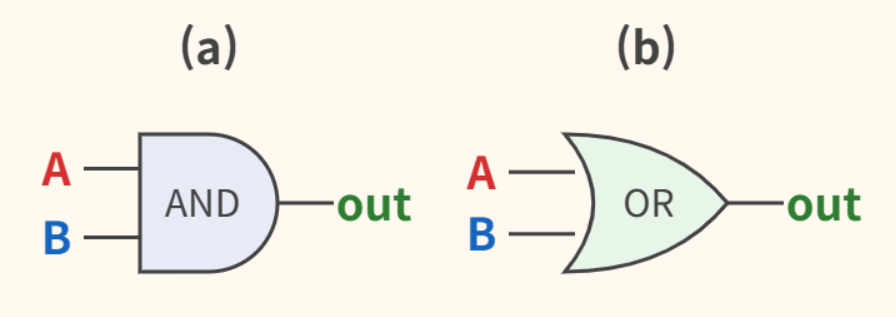
Because these circuits are used over and over inside a chip, drawing out every transistor each time would be tedious. So we leave the circuits themselves as they are and represent the same functions with simple symbols. Raising things one level of abstraction (modularization) like this, we represent them not at the level of transistors but at the level of gates, as in Figure 3-11. Now, when you look at the symbols in Figure 3-11 below, you can think of each one as standing for a circuit of connected transistors like those we’ve just seen.
Starting from a circuit with a light bulb and a switch, we agreed to call low voltage 0 and high voltage 1, and went on to abstract certain transistor arrangements in a circuit under the name of basic logic circuits. These abstracted basic logic circuits, in turn, become the foundation for understanding more complex circuits built by connecting them. We can now move beyond focusing on the voltage at each point or the behavior of physical transistors, and extend our thinking in logical terms. Still, we should keep in mind that underneath it all lies an electronic circuit.
Isn’t that a little surprising? By understanding basic logic circuits, we’ve taken the first step toward seeing how the chip — the brain of the computer — is put together.
One downside of abstraction is that it can be hard to understand without a detailed explanation of what’s inside; on the other hand, its power lies in letting us set the complexity aside and move easily on to the next step. In the next chapter, we’ll see how these basic logic circuits are combined and developed into circuits with more complex functions.