3.2 The Transistor, a Switch Driven by Voltage
The bulb-and-switch circuit in the previous section is an electric circuit. But we also often hear the term electronic circuit. An electronic circuit is a kind of electric circuit too, but instead of a person pressing a switch by hand, it contains components that control the flow of electricity with voltage. In an electronic circuit, these components represent states by changing voltages throughout the circuit. The best-known such component is the transistor.
Figure 3-4 (a) shows a physical transistor, and (b) shows the symbol used for a transistor.
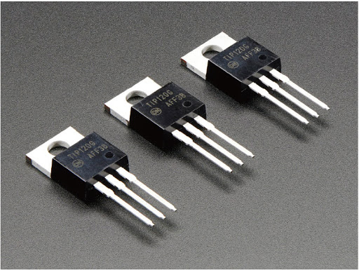
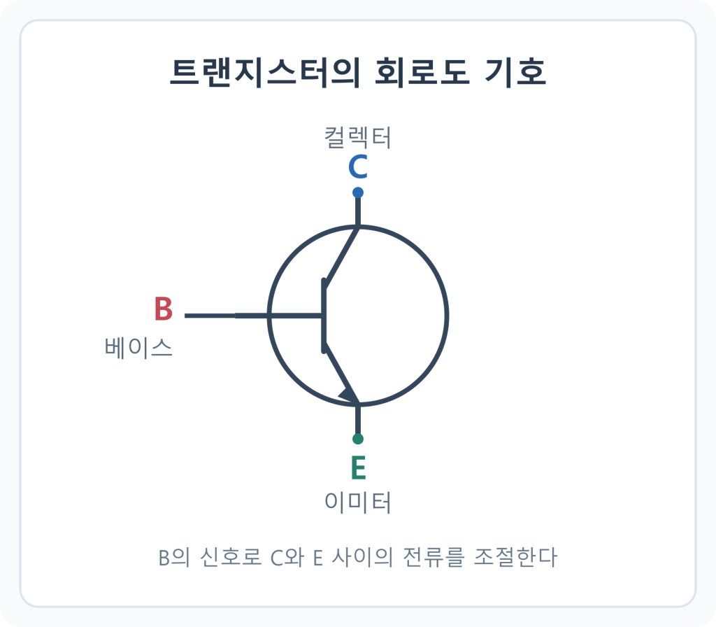
Figure 3-4. (a) A physical transistor (b) Its circuit symbol
A transistor connects or breaks a path in a circuit depending on a condition. In other words, it works much like the switch in Figure 3-1.
A switch was a component that a person pressed by hand to physically connect a path so current could flow, or released to stop it. A transistor uses voltage instead of a hand. In Figure 3-4 (b), if you supply voltage to B and raise its voltage, C and E are connected, as if a switch had closed, and current flows. Supplying voltage to a point like this is technically called applying a voltage. Conversely, if no voltage is applied to B and its voltage is low, C and E are disconnected. If you connected C and E of this transistor to where the switch was in Figure 3-1, the bulb would turn on or off depending on whether voltage is applied to B. Depending on B’s voltage, the transistor acts as a switch between C and E. Quite an interesting component.
Now let’s look at an electronic circuit made by connecting two transistors. It may look a little complicated at first, but as with everything, it’s nothing once you understand it, so take your time. In Figure 3-5, two transistors are connected; A and B are inputs to which voltage is applied, and out is the output whose voltage ends up high or low as a result. Let’s see how the voltage at each point in Figure 3-5 is determined.
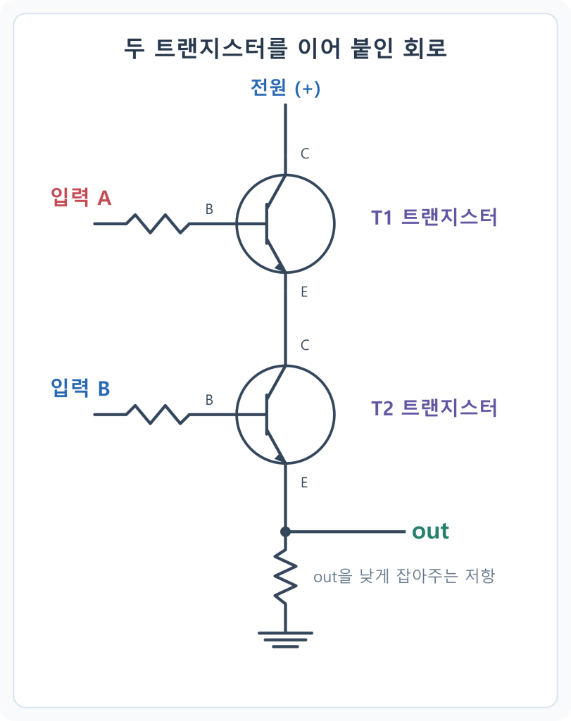
As Figure 3-5 shows, C of transistor T1 is connected to the power supply, so its voltage is always high. In this state, 1) let’s apply voltage to inputs A and B at the same time. Then imagine whether out’s voltage will rise or stay low as a result.
Analyzing it slowly, here’s what happens. When input A applies voltage to B of T1, T1 closes and connects C and E. Then C of T2, which is connected to E of T1, is also connected to the power supply, and its voltage rises. In this state, when input B applies voltage to B of T2, T2 closes as well, and in the end out, too, is connected to the power supply.
To sum up: when voltage is applied to inputs A and B at the same time, both transistors close, out is connected to the power supply, and out’s voltage rises — case 1).
This time, let’s apply voltage only to input B and not to input A. T2 closes, but T1 is open, so C of T2 can’t connect to the power supply. As a result, out can’t connect to the power supply either, and its voltage stays low — case 2). In the same way, you can work out what happens to out’s voltage when voltage is applied only to input A — case 3) — and when it’s applied to neither — case 4). All the cases are summarized in Table 3-1 below.
| A | B | out | Case |
|---|---|---|---|
| 0 | 0 | 0 | 4) |
| 0 | 1 | 0 | 2) |
| 1 | 0 | 0 | 3) |
| 1 | 1 | 1 | 1) |
Table 3-1 expresses a voltage below the threshold as 0 and above it as 1, as we learned earlier. Looking at it, we can see that in the circuit of Figure 3-5, where two transistors are connected, out’s voltage rises only when voltage is applied to inputs A and B at the same time; in every other case, out’s voltage stays low.
There are two things worth noting here. First, once the voltages of inputs A and B are set, out’s voltage is always determined by the same rule. Second, an electronic circuit built from transistors like this can represent states through combinations of voltages. A single transistor has only two states, closed and open, but by connecting two, we can now represent four states.
So far, we’ve looked at the transistor and at electronic circuits made by connecting transistors.
This sudden detour into transistor circuits may have felt unfamiliar, but there’s a reason for it. As you’ll soon see, the chips in the world beneath the code that we’re trying to understand are, ultimately, electronic circuits made of tens of billions of transistors connected together.